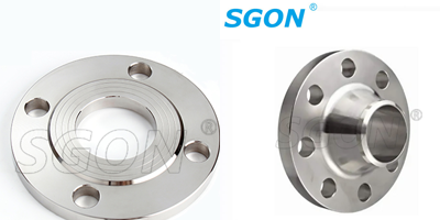
Flanges play a crucial role in the connection of pipes and various industrial equipment. The design of flanges involves a careful balance of multiple factors to ensure reliable performance, safety, and cost-effectiveness. This article delves into the essential considerations in flange dimensioning and the key points of structural optimization.
I. Dimensioning Considerations
A. Nominal Pipe Size (NPS) and Pressure Rating
The starting point in flange design is determining the nominal pipe size and the required pressure rating. The NPS dictates the basic dimensions of the flange, such as the bolt circle diameter and the flange thickness. For example, a larger NPS will generally require a wider bolt circle to provide sufficient clamping force. The pressure rating, which is related to the maximum operating pressure of the system, determines the thickness and strength of the flange. A higher pressure rating demands a thicker flange body and stronger bolt connections to withstand the internal pressure. For instance, in a high-pressure oil and gas pipeline, the flange must be designed to handle pressures exceeding several hundred pounds per square inch (psi), necessitating robust dimensions and precise engineering.
B. Bolt Hole Configuration
The number, size, and spacing of bolt holes are critical dimensions. The number of bolts is typically chosen based on the flange size and the required clamping force. Larger flanges usually have more bolt holes to evenly distribute the load. The bolt hole size must be appropriate for the selected bolts, allowing for proper installation and torque application. The spacing between bolt holes, known as the pitch circle diameter, affects the overall strength and balance of the flange connection. Incorrect bolt hole spacing can lead to uneven stress distribution and potential leakage. For example, in a flange used in a chemical processing plant, where corrosive fluids are involved, proper bolt hole configuration is essential to maintain a tight seal and prevent any leakage that could have catastrophic consequences.
C. Flange Face Type
The choice of flange face type is another important dimension consideration. Common flange face types include flat face, raised face, and ring joint face. The flat face flange is suitable for low-pressure applications where a simple and cost-effective connection is sufficient. The raised face flange provides a better sealing surface and is widely used in moderate-pressure systems. The ring joint face flange, with its precision-machined groove for a metal ring gasket, is designed for high-pressure and high-temperature applications where a more reliable seal is required. For example, in a steam power plant, where steam is at high pressure and temperature, ring joint face flanges are often employed to ensure leak-free operation.
II. Structural Optimization Points
A. Minimizing Weight without Compromising Strength
In many applications, reducing the weight of the flange can have significant benefits, such as lower material costs and easier installation. However, this must be done without sacrificing the strength and integrity of the connection. One approach is to use finite element analysis (FEA) to optimize the flange geometry. By simulating different load conditions and stress distributions, engineers can identify areas where material can be removed or redistributed. For example, in the design of flanges for aeroengine piping systems, where weight reduction is crucial for fuel efficiency and overall performance, FEA is used to create lightweight yet structurally sound flange designs.
B. Improving Stress Distribution
Uneven stress distribution in a flange can lead to premature failure. To optimize stress distribution, the flange geometry can be modified. For instance, adding fillets or chamfers at critical areas can reduce stress concentrations. The thickness of the flange can also be varied in a tapered manner to better distribute the load. In addition, the use of reinforcing ribs or stiffeners can enhance the rigidity of the flange and improve stress distribution. For example, in a large-diameter water pipeline flange, where significant external forces and internal pressures act, proper stress distribution optimization techniques are employed to ensure a long service life.
C. Sealability Enhancement
The sealing performance of a flange is of utmost importance. Structural optimization can be done to improve sealability. This includes ensuring a precise mating surface between the flange and the gasket. The flange face can be machined to a high degree of flatness and smoothness. Additionally, the design of the flange groove for the gasket, if applicable, can be optimized to provide a better fit and sealing force. For example, in a flange used in a pharmaceutical manufacturing plant, where strict hygiene and leak-free requirements are in place, sealability optimization is a top priority to prevent any contamination of the product.
In conclusion, flange design is a complex and multidisciplinary process. By carefully considering the dimensioning factors and implementing structural optimization techniques, engineers can create flanges that meet the specific requirements of different industrial applications, ensuring reliable and efficient pipe connections.

GET A QUOTE